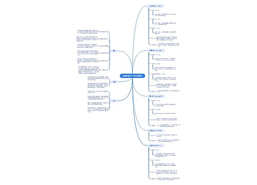
Process Design Considerations of Stem Breaking for Damage Reduction in Extracted Natural Fibers 思维导图
U947057588
2023-10-06

材料和方法
跨度长度
刀具偏转
断干降低提取天然纤维损伤的工艺详解
树图思维导图提供《Process Design Considerations of Stem Breaking for Damage Reduction in Extracted Natural Fibers 》在线思维导图免费制作,点击“编辑”按钮,可对《Process Design Considerations of Stem Breaking for Damage Reduction in Extracted Natural Fibers 》进行在线思维导图编辑,本思维导图属于思维导图模板主题,文件编号是:d1d051e92e716197436aa781503cb0c3
思维导图大纲
相关思维导图模版
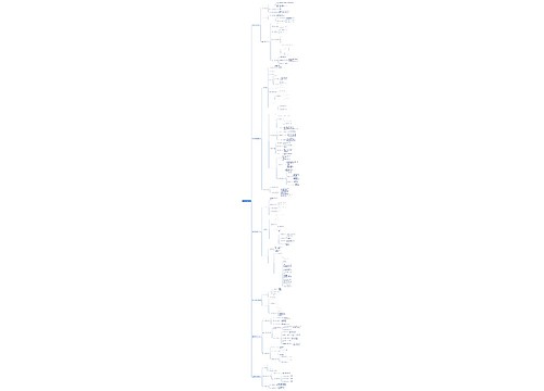
Process Design Considerations of Stem Breaking for Damage Reduction in Extracted Natural Fibers 思维导图模板大纲
Anshul Singhal1, Mihaela Banu2 and Alan Taub1,2
ABSTRACT
Plant based fibers such as flax have the potential to replace glass as sustainable reinforcement in polymer composites. However, these fibers face high amount of damage during current mechanical extraction, leading to high variability in their mechanical properties, and making it difficult to implement them in composites for structural applications. While prior studies mainly focus on defect analysis or improving mechanical extraction at industrial level, our aim in this research is to understand the underlying mechanism of fracturing of these stems during mechanical extraction that leads to fiber damage. Here, compression and bending tests of single retted flax stems were done along with visual observation of fracturing inside woody core. Further, bending analysis of stems under wide tool geometry using finite element modeling (FEM) was done and used as a guide to design of an improved roller profile for lab scale stem breaker. Insights developed from compression and bending tests were used to develop improved breaking process steps with optimal stem compression and roller gap. Fibers were extracted from the improved breaking process and significant improvement in tensile properties were seen when compared to fibers extracted under high bending strains.
_____________
1Materials Science & Engineering, The University of Michigan, 2300 Hayward St, Ann Arbor, MI, 48109, USA.
2Mechanical Engineering, The University of Michigan, 2350 Hayward St. Ann Arbor, MI 48109, USA.
Introduction
With increasing amount of global CO2 levels, demand of carbon negative materials has significantly increased []. Natural fibers such as flax which are found on the outer bast region of the plant stem are gaining importance as a carbon negative resource in polymer composites. These outer bast fibers are extracted as technical fibers, which are group of single elementary fiber cells joined together by pectin rich middle lamella interphase and compared to synthetic fibers such as glass, their extraction is much less energy extensive[]. Besides having high specific modulus and tensile strength, main challenge in implementing these fibers in industry scale structural composites applications is the high variability in their properties that limits the composite design to their lower bound of mechanical properties[].
Over hundreds of years, major use of these natural fibers is found in textile clothing application and the same commercial extraction process is currently used for extracting fiber for their use in composites []. Here, first these stems go through a process called dew retting, where the plant stems are put into the farm field for about 8-10 weeks and degradation of the pectin rich interphase that binds these fibers to the inside woody core occurs by microbial activity in the field[]. This reduces the energy and fiber damage during the next mechanical breaking step, where, these retted stems are crushed between the gear teeth or flute profile of rotating rollers, to break and separate the inside brittle woody core from the bast fiber layer[]. Extracted bast fiber layers or strips then goes through cleaning and refining steps. Here, shaking and scutching is done to remove any remaining woody core material, following by hackling where these bast fiber strips are put into combing action between pins to align and divide the bast strips into finer technical fibers[].
While this current fiber extraction method is commercially viable for textile application, it degrades the natural fiber quality a lot from its original potential []. The dew retting process is weather dependent and divides the bast bundles non-uniformly. Moreover, enzymes secreted by micro-organisms damages cellulose, the structural component of these fibers in addition to the required pectin bond []. To overcome the challenges in dew retting, researchers in the past have extensively studied the use of specific enzymes to degrade specific components in plants for controlled retting, such as pectinase to degrade pectin, laccase to degrades lignin or cellulase to degrade cellulose[jana]. Studying these enzymatic retting on various plants like flax [] and hemp [], shows that using a pectinase like polygalacturonase provides efficient bast separation with minimal effects on mechanical properties of natural fibers [].
In addition to retting, mechanical extraction steps, particularly breaking [], induces fiber damage and bending defects such as kink band, leading to degradation and high variation in mechanical properties of these fibers []. Prior studies include characterization of these defects and its effect on fiber properties. Beaugrand et al. studied these damage mechanisms at submicron level using X-ray tomography. Hänninen et al. and Estrada et al. characterized bending defects in flax and hemp fibers using polarized light microcopy and acid hydrolysis methods. Also, several studies have done on improving mechanical extraction equipment, such as helical geared design of breaking rollers by Wang et al [], lab scale pilot plant for flax processing by Akin et al. [], virtual environment studies of hemp fiber production line using TRIZ by Xu et al. [] and finite element modeling of processing equipment by Olan et al. []. While most of these studies focus on either studying defects or improving the breaking equipment with change in equipment configuration, limited to no studies were found for fracture mechanism occurring during breaking of these stems at fundamental level that can guide the process and equipment design for mechanical extraction of natural fibers with minimal damage and defects.
Our current research aims to evaluate the fiber damage occurring at single stem level during mechanical breaking and develop best practices for high quality natural fiber extraction. In this study, enzymatic retting with pectinase enzyme aiming to specifically degrade the pectin glue between fibers and woody core is used for lab scale-controlled retting. Fracturing of retted stems under pure compression and bending were studied using compression and 3-point bending tests. Analysis of stem bending under a wide tool geometry was done using finite element modelling (FEM) and improved breaking process with a novel prototype roller profile was designed. Lastly, impact of this improved stem breaking process on extracted fiber properties was evaluated.
Materials and methods
Flax stems
Raw flax stems of Agatha variety used in this study were grown under uniform conditions at Orgon State University research farm in 2019 spring and provided by FibrevolutionTM. Also, for uniformity in sampling through experiments, the middle 25 cm long section of these stems with diameter 1.5 ± 0.1mm was chosen for enzyme retting[].
Enzymatic retting and fiber extraction
Pectinex® Ultra SPL (procured from Sigma Aldrich) with enzyme activity equal or greater than 3,800 units/mL according to product data sheet was used for lab scale retting of raw flax stems. Enzyme-buffer solution of 0.5% (v/v) was prepared with sodium acetate buffer (0.05 M, 4.5 pH) and flax stems taken in 1:25 ratio (gm:ml) with this enzyme solution in a test tube at room temperature, following by incubation at 40 °C for a duration of 24 hours while shaking horizontally at 100 rpm. Flax stems were gently washed after retting five times with distilled water and dried at 100 °C for 24hr before any mechanical testing or fiber extraction.
Technical fiber bast strips were carefully extracted manually or through breaking stems under rolling depending on different experiments in this study. These bast strips were then hackled into finer technical fibers using a pin frog (9 pins/cm2) and kept at 50% relative humidity at 23 °C in a humidity chamber for conditioning prior tensile testing.
Single technical fiber microscopy and tensile testing
ASTM C1557 – 14 standard was used for sample preparation and testing single technical fibers. Here, 15 randomly selected fibers were mounted on paper frame tabs using cyanoacrylate adhesive at 10 mm gauge length to reduce the elementary fiber interphase contribution []. Optical microscopy was done on mounted fibers using Olympus DSX510 digital microscope in polarized light (PO) mode, first front view and later rotating the fiber 90 degrees for side view. Average of 8 measurements along each direction was used to estimate the respective diameters and ellipse approximation was used to calculate the cross-sectional area of technical fibers here, used in prior studies for better evaluating the tensile properties of fibers []. Later, tensile tests on conditioned extracted fibers were performed by using a Texture Analyzer from Texture Technologies Corp. with a 50 N load cell capacity. The paper mount was cut after mounting the fibers in the tensile grips and crosshead speed of 0.01 mm/sec was chosen with trigger force of 0.03 N for the tensile test. The tensile data was corrected for initial slack in elongation and system compliance (calculated using a stiff specimen under tensile testing with same parameters as fiber test) for better estimation of modulus.
Stem fracture analysis under pure compression & three-point bending
Radial compression test on 1.25 cm long retted stem samples was done using Texture Analyzer from Texture Technologies Corp. with a 300 N load cell and the fracture events were monitored through video recording. Initial diameter at start of compression is determined by trigger force of 0.3 N and stems were compressed under parallel plates (25 mm in diameter) to a maximum force of 80 N with test speed of 0.05 mm/sec maintained during the whole compression-decompression cycle. To compare the compression of stems under parallel plates with the compression under rolling between flat rollers (65 mm roller diameter) of a rolling mill, rotating at 0.55 rpm, two samples were taken adjacent to each other from a single retted stem, where repeatability in mechanical tests established in prior studies [] and exposed to equal amount of compression through both the processes. Then compression test using Texture Analyzer were performed on compressed samples to observe the difference in force-compression curve. Additionally, to evaluate the effect of pure compression under flat rolling on fiber properties, single fiber tensile tests were performed on fibers extracted from enzyme retted stem for the evaluation of overall improved extraction with enzymatic retting.
Retted stems were also subjected to pure 3-point bending using a Dynamic Mechanical Analyzer or DMA (RSA-3 by TA Instruments) having 34 N load cell capacity. Span lengths of 25 mm and 40 mm were chosen according to ASTM D 790, having high enough span length to stem diameter ratio to avoid shear effects []. Tool geometry consists of chisel tip with a 0.1 mm tip diameter. Stem lengths were taken about 20-25 % longer than of support span length. The deflection of load tool was set at 0.05 mm/sec and 0.01 N was taken as trigger force for test start. The estimation of bending radius for both span length case at max force is done using equation (1), derived from simple geometric calculations:
![Diagram
(1)
where,
rc = radius of curvature during bending
s = span length
y = tool deflection
Also, from prior studies by Baley et. al., considering stem or woody core as beams with hollow circular cross-section, the bending stiffness at lower strains is proportional to the slope of force-deflection curve by equation (2) [].
(2)
where,
E = apparent bending modulus
I = area moment of inertia
F = recorded force value
Three-point bending with wide tool geometry study through finite element analysis (FEA)
Industrial rollers have gears geometry with flutes width much larger than the stem diameter. To study the bending of stems under a wide tool geometry of 3-point bend, static finite element modeling (FEM) was done using software ABAQUS/standard. Here, a hollow tube of length 60 mm with outside and inside diameter of 1.32 mm and 0.84 mm respectively was used for simplified model of woody core. These dimensions were calculated as average from 5 cross-section diameter measurements of woody core under optical microscope. The aim of this simplified mechanical model is to provide guidance in studying effects such as strain behavior from varying tool configurations during bending. The experimental curves for force-displacement from pure compression and bending tests were used to determine the constitutive material parameters of orthotropic stiffness matrix of woody core for FEM. Woody core was meshed using C3D8R element type with 10 elements along circumferential thickness and 217,800 in total elements. Analytical rigid body shell was used for modelling different tool profiles in FEM and general contact interaction property with 0.1 frictional coefficient (µ), tangential & normal behavior was used between tool - woody core interphase. Amplitude time step of 1 mm deflection is applied as load on top tool. Bending cases studied under FEM were also experimentally studied by creating similar tool profiles using 3D-printing with PLA material (stiffness much higher than flax stems) for stem bending tests using DMA.
Improved stem breaking and extracted fiber characterization
Based on the bending studies, an improved stem breaking process with improved flute profile of prototype roller was designed for fiber extraction. Moreover, bending of enzyme retted stems from this improved breaking roller profile was studied by creating a similar tool geometry in DMA bending tests. The prototype rollers profile geometry was constraint to work with the equivalent flat roller of 65 mm diameter in the rolling mill, previously used during compression study. Also, breaking rollers with circular flute channel profile are commonly used for stem breaking [] and prototyped here as poor roller profile for baseline comparison. Then, a controlled experiment was done to study extracted fiber properties from both breaking roller profiles. Here, two stem samples of 5 cm each was taken from middle section of a single retted stem and passed three times from a pair of fluted rollers in breaker rotating at 0.55 rpm, one with poor and other with improved roller profile respectively to break & separate the woody core from the bast layer. Then, manual shaking of these bast strips were done to remove any remaining attached woody core material followed by hackling into finer technical fibers. 3D-printing using PLA material was used for prototyping the roller and tool geometry in DMA tests.
For characterization, single fiber tensile tests were carried out on extracted fibers from both breaking rollers’ profile. Additionally, for visualizing the mechanism of fiber damage in case of mechanical extraction from poor roller profile, scanning electron microscopy (SEM) was done. Here, extracted fibers were first mounted on flat metal stubs with adhesive carbon tape and sputter coated with 30 nm thick layer of gold-palladium. JEOL IT500 scanning electron microscope was used to visualize the morphology of fibers at 10 kV accelerating voltage under high vacuum.
Statistical analysis
For multiple pairwise mean significance comparisons in this study, two-sample T-Test was done using R Studio software. Significance threshold was taken as 95% confidence interval, where a p-value < 0.05 indicates the rejection of null hypothesis and the mean differences to be statistically significant. For expressing results significance labeling was done using letter notation, where means having same letter (a, b, etc.) were statistically not significantly different.
Results and discussion
a
MON
0
MON
1
MON
1
MON
1
MON
1
MON
0
MON
0
Stem fracture studies under pure compression and bending
The force - compression curve for a single compression-decompression cycle of a whole flax stem sample in Figure 1a and corresponding events occurring are shown in Figure 1b. Here, flax stem shows an initial linear elastic behavior followed by non-linear behavior with top & bottom fracturing of inside woody core occurring due to local buckling at events 2, 3 in region I. Further compression in region II, shows the sideway splitting of both bast layer and woody core at event 4 and over-compression of region I fractured core. It can be concluded over here that about 30-40% of compression is required to achieve the optimal fracturing of woody core under flat rolling to avoid damage to stems and bast fibers by over compression.
Moreover, to observe the mimicking of stems under parallel plate compression with the flat rolling compression, the force-compression curve of the two adjacent samples from a single retted flax stem, each pre-compressed to 35% limit of previously shown region I with respective method of compression, are compared in Figure 1a. Here, the force-compression curve of these two samples correlated well with each other, hence, parallel plate compression can give a good estimate of stem fracturing under flat rolling compression.
![Diagram
Figure (a) Force-compression curve for retted flax stem before and after pre-compression (b) Visual observation of events occurring at various points during compression
Furthermore, Table 1, shows the fiber properties of manually extracted and hackled bast strips from whole (SL24 (M)) and 35% pre-rolled (SL24 (C+M)) enzyme retted stems. Here, cross-sectional area, modulus, and tensile strength of technical fibers from both groups found statistically comparable (p > 0.1), which shows that fiber properties remain unaffected under pure compression within 35% of region I (figure 1) during rolling between flat rollers. Also, reduction in variation or relative standard deviation in % is observed in case of fiber properties from rolled stems, indicating reduced variation in manual peeling of bast strips after pre-compression.
Table 1
T
Area
Modulus
Tensile Strength
(um2)
(GPa)
(MPa)
SL24 (M)
8030 ± 4698(59 %) a
47.7 ± 9.5(20 %) a
889 ± 253(28 %)a
SL24 (C+M)
6134 ± 2677(43 %) a
43.6 ± 7.6(17%) a
880 ± 207(24%) a
Values within a column followed by the same letter are not significantly different (p > 0.05)
Figure 2 shows the force- deflection curve of stem fracturing under pure 3-point bending for 40 mm and 25 mm spans. Initial linear elastic region is seen in bending under both spans, where slope of the curve during 25 mm span bending is higher than 40 mm span, and hence, the bending stiffness, which leads to more catastrophic failure due to lower displacement of central point, and a lower loss in initial linearity before breaking when compared to 40 mm bending. This loss in linearity at higher span bending was also observed in previous studies by Baley et al []. While bending stiffness increases by lowering the span, the deflection of the tool needed to reach fracture also reduces. Further, evaluating of radius of curvature at time of initial fracturing for both the spans shows similar results, indicating similar strains at the time of initial fracture. This evaluation of changing bending stiffness with spans guides in estimating optimal tool deflection or roller gap for stem fracturing under bending, especially in case of small diameter rollers where the pitch of flutes (support span) is small and tight roller gap (high deflection) can cause high bending strains due to high bending stiffness, leading to defects such as kinks in bast layer fibers.
![Chart
Figure 2
F
Three-point bending of stems with wide tool geometry
To visualize the effect of bending under 3-point geometry with wider tool, finite element model (FEM) for the stem woody core is created using ABAQUS as shown in Figure 3a. Here 45 mm support span is chosen, where each support tool is 5 mm wide with 5 mm radius of curvature. A 15 mm wide geometry with large radius of curvature is chosen for top load tool. Further, Figure 3b shows an equivalent 4- point bend model with similar support span and top load span of 45 mm and 15 mm respectively, having all tool dimensions being 5 mm in width with 5 mm radius of curvature. Woody core is modelled as orthotropic elastic material and constitutive material parameters are summarized in Table 2. Here, both the models show similar elastic strain (EE) throughout the woody core along with two high strain regions at the tool contact points.
![Graphical user interface, application
Figure 3
F
Table 2
E
E1=E2
MPa
E3
MPa
N12
N23=N13
G12 (f (E1))
MPa
G13=G23
MPa
100
670
0.56
0.04
32
116
The maximum principal elastic strain (EE) along the linear nodal path at top middle section of woody core is taken as output from ABAQUS for 0.1 mm top tool deflection from both the models and compared in Figure 4. Here, both the models show similar compressive strain curve for top part of woody core, where the strain increases from support to load span followed by a constant strain region along the width of wider load tool or between the load span tools in case of 4-point bending. Also, the curve shows two high strain regions as spikes in both the models at the tool contact points. This shows that the 3-point bending of stems under wider tool is essentially similar to the bending under 4 - point geometry, where the load span between top two tools is equivalent to the width of the 3-point load tool.
![Chart, line chart
Figure 4
C
Furthermore, for experimental studies, similar load and support tools configuration discussed in above two cases are created for bending of stem samples (taken from a single flax stem) using DMA and the force- deflection curves are summarized in Figure 5. Here, initial linear elastic region of force-deflection curve from 3-point wide tool geometry correlated well with the 4-point tool bending curve and the major fracturing event in both the cases seen around 1.5 mm of tool deflection. However, a 4-point geometry here, allows more displacement of center point, causing higher non-linearity and gradual forces drop leading to a less catastrophic failure than a 3-point wide tool geometry. We hypothesis that this is due the middle gap between top tools allowing for the bast layer to buckle, while giving space to inside woody core to fracture gradually.
![Chart, histogram
Figure 5
F
Improved roller profile and effect of compression on stems prior bending
Taking guidance from studies in prior section, a 4-point bend geometry is considered in designing improved flute profile for protyping breaker rollers. Figure 6 shows the poor and improved roller profile along with corresponding meshing of flutes during rolling operation. The various geometric parameters for both roller profiles are summarized in Table 3. Circular flute channel geometry, taken here as poor roller profile had a narrow clearance between the tools during closing and induces high bending strains when compared to the improved roller profile for same deflection of tool.
![Diagram
Figure 6
(
Table 3
r
Poor Profile
Improved Profile
Outside diameter (Do)
69.6 mm
69.5 mm
Inside diameter (Di)
60.4 mm
58.1 mm
No of Flutes (#)
22
10
Tool radius (r)
2.3 mm
2 mm
Tool width (w)
4.5 mm (~2r)
8 mm (~4r)
Tool Height (h)
4.6 mm ((Do-Di)/2)
5.7 mm
Load span (a)
-
4 mm (~2r)
Support span (s)
9.4 mm (~4r)
16 mm
Inner span width (si)
4.8 mm
12 mm
Ratio s:a
-
4:1
Closing tool clearance (c)
0.15 mm ((si – w)/2 )
2 mm
Figure 7
Figure 7
F
Fiber extraction through improved mechanical breaking and property evaluation
Based on studies in previous sections, following steps are considered for improved breaking process with prototype rollers here:
Compression of retted stem samples to 35 % under rolling between flat rollers to reduce the stiffness of woody core.
Breaking compressed stems under bending between rollers with improved profile, to break and separate the woody core from bast. Roller gap is kept such to maintain 3 mm maximum tool deflection during stem bending.
Shaking and hackling of extracted bast layers to finer technical fibers.
These steps were repeated with poor roller profile for baseline comparison and the tensile test results for fibers extracted from both poor and improved roller profile in breaking process are summarized in Table 4. Here, cross-sectional area of fibers was comparable between the two different roller profile case of extraction (p > 0.5), as it depends upon initial retting condition which was same. But both tensile modulus and strength were significantly lower (p < 0.001) in case of fibers extracted using poor roller profile. Further, reduction of variability or relative standard deviation in % in modulus and area is observed in case of extraction from poor roller profile, an effect observed in prior studies as well where excessive mechanical beating of fibers during mechanical extraction reduces the strength and variability when compared to carefully hand extracted fibers [jana].
Table 4
T
Area
Modulus
Tensile Strength
(um2)
(GPa)
(MPa)
SL24 (Poor)
6563 ± 1993(30%) a
37.6 ± 6.5(17%) a
350 ± 179(51%) a
SL24 (Improved)
6841 ± 3039(44%) a
52.5 ± 11.8(22%) b
1032 ± 231(22%) b
Values within a column followed by the same letter are not significantly different (p > 0.05)
Figure 8 shows the scanning electron micrographs (SEM) for extracted fibers from the two cases of roller profile. Here permanent deformation under excessive bending is observed in fibers extracted from poor roller profile (Figure 8 (a, b)), when compared to fibers extracted from improved roller profile which were found mostly aligned straight (Figure 8 (c, d)). Also, besides kink bands, splitting of technical fibers is observed as damage mechanism in fibers extracted from poor roller profile, indicating the weakening of elementary fiber cells interphases within technical fiber bundle under high mechanical bending strains, thus affecting the overall integrity of the technical fiber and hence reduction in tensile strength and modulus.
Figure 8
S
Conclusion
Fracture occurring within a retted flax stem during mechanical extraction step called breaking was studied by testing retted stem samples under pure compression and bending. Correlating fracture events in force-compression curve during pure compression with visual fracture observation gave insights into the ideal compression limit (~ 30-40 %) needed to optimally fracture the inside woody core and avoid damage from over compression. Further, compression under parallel plate was found to have similar force-compression curves with compression under flat rolling, and compression within the optimal limit showed to have no significant effect on tensile properties of enzyme retted fibers.
Effect of changing length of support span was studied during pure 3-point bending tests of retted stems, where bending radius of curvature leading to fracture found to be similar between different spans. The 3-point bending with wide tool geometry was studied through finite element analysis (FEA) along with experiments and found to be equivalent to a 4-point bending geometry. An improved roller profile with 4-point bending geometry was designed for prototyping breaker rollers and importance of pre-compressing stems prior breaking was illustrated. For baseline comparison, a poor roller profile was created to subject stems under high bending strains and fibers extracted from both breaking rollers were characterized for tensile properties. Poor breaking roller profile significantly degrade the fiber modulus and tensile strength. Further, microscopic observation under scanning electron microscope (SEM) showed permanent bending deformations in fibers extracted from poor roller profile. Here along with kink band defects and splitting of technical fibers was seen, indicating damage to inside elementary fiber cell interphases under high bending strains. Lastly, we believe that taking the guidance from single stem fracture studies here, it possible to design the extraction process on large scale for future studies to extract fibers from stem bundles with minimal damage for green structural composites.
Acknowledgement
The authors would like to acknowledge the financial and technical support from University of Michigan College of Engineering, Global CO2 initiative and Materials Science and Engineering Van Vlack Laboratory at University of Michigan.
References
查看更多
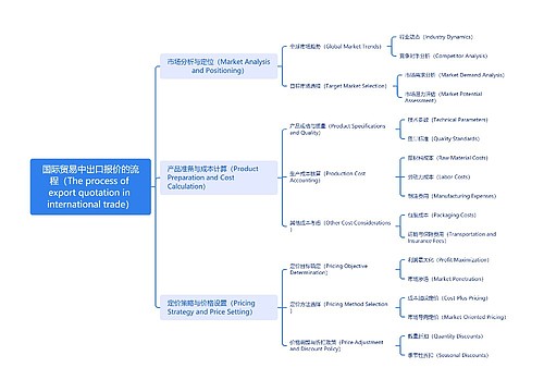
国际贸易中出口报价的流程(The process of export quotation in international trade)思维导图
 U777032255
树图思维导图提供《国际贸易中出口报价的流程(The process of export quotation in international trade)》在线思维导图免费制作,点击“编辑”按钮,可对《国际贸易中出口报价的流程(The process of export quotation in international trade)》进行在线思维导图编辑,本思维导图属于思维导图模板主题,文件编号是:5de79042f72c55903c8b7d7401d541d2
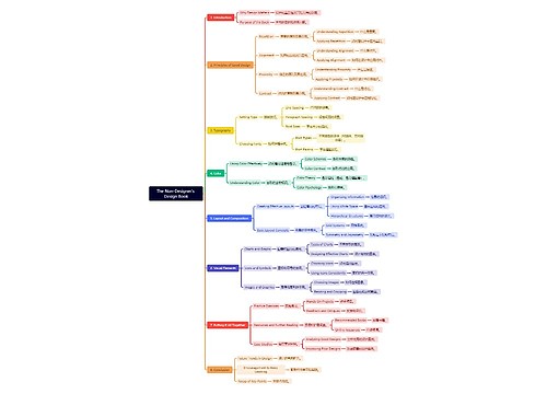
The Non-Designer's Design Book思维导图
 U879677142
树图思维导图提供《The Non-Designer's Design Book》在线思维导图免费制作,点击“编辑”按钮,可对《The Non-Designer's Design Book》进行在线思维导图编辑,本思维导图属于思维导图模板主题,文件编号是:009d2cc7242af8dbba498815ff8abdbd
相似思维导图模版
首页
我的文件
我的团队
个人中心
